
Campus Power Model
Plan Power, Compute, Cooling, Connectivity, and Operations as One Campus.
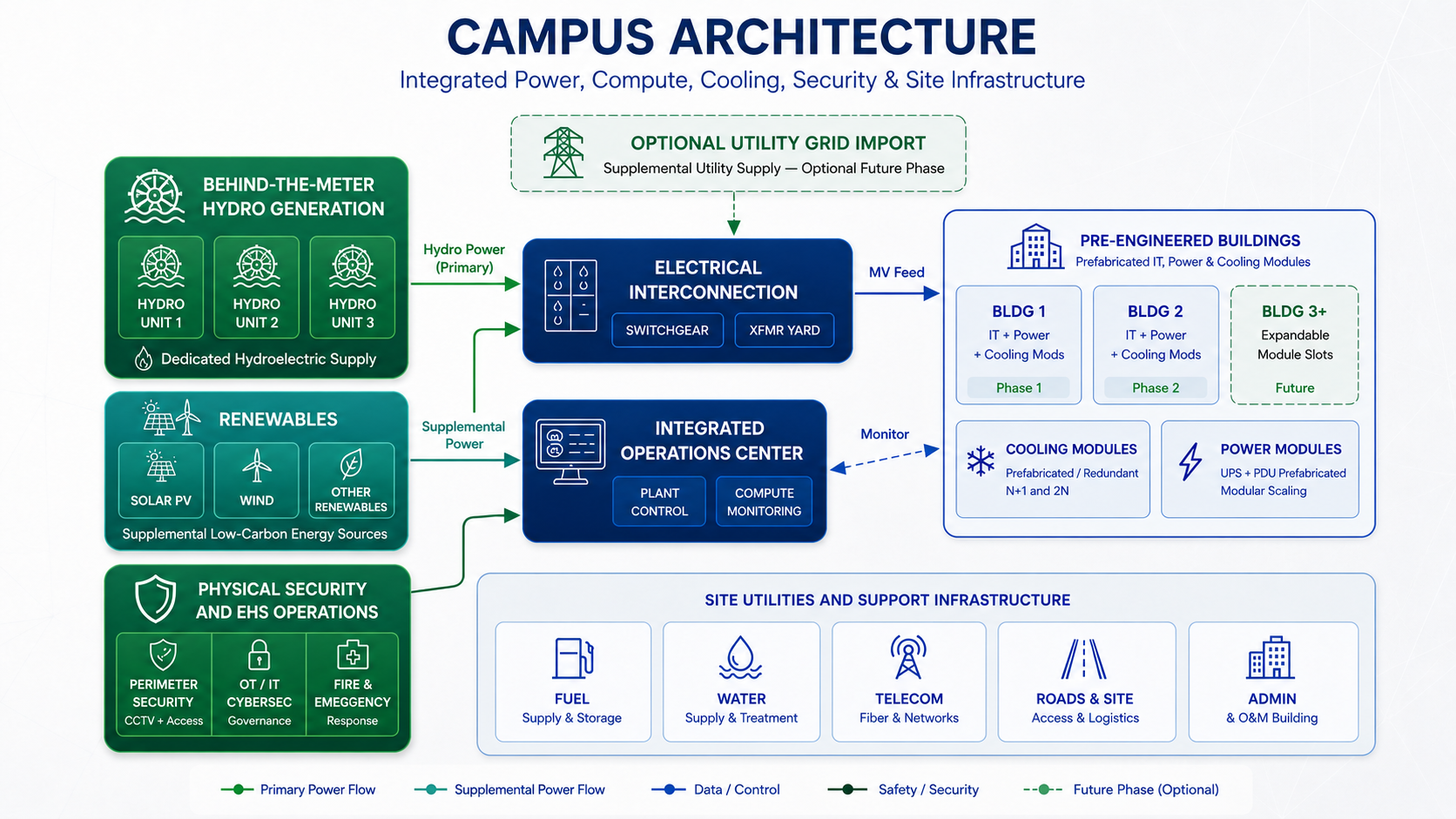
Sovereign Shield Energy Compute Campus is being developed as an integrated Canadian compute campus: hydro-backed power strategy, campus-scale electrical distribution, high-density compute buildings, cooling infrastructure, carrier access, security, and operations planned together from the beginning. The objective is to reduce the interface risk that appears when power, buildings, networks, and operations are procured as separate, disconnected systems.
Gigawatt+
Delivered Capacity
Phased across 7 phases
Hydro
Power Source
Renewable, Canadian-controlled
2×
Independent MV Distribution Paths
A and B, continuously energized
24/7
Operations Coverage
Plant, compute, security
The Conventional Approach
Traditional Data Center Power Design Has a Structural Problem
The conventional model made sense for an earlier era. It is not the right architecture for gigawatt-scale AI and HPC campuses.
Most data centers are built on a familiar model: utility power as the primary source, a farm of standby generators as backup, and a transfer-based architecture that connects them. Halls are designed independently. Electrical systems are assembled by domain rather than planned as a campus. Utility availability is assumed, not engineered around.
At moderate scale, this model functions. At gigawatt scale — with large AI training clusters, high-density HPC, and multi-year deployment horizons — its constraints become structural liabilities: utility queue exposure, fragmented distribution, backup-power thinking embedded in the architecture, and limited ability to expand without revisiting the entire electrical strategy.
Utility Dependency
Large deployments face multi-year interconnection queues. Utility availability determines deployment timing, not the other way around.
Fragmented Distribution
Hall-by-hall generator and UPS design creates inconsistent power paths, complex switchgear coordination, and difficult expansion logic.
Backup-Power Architecture
Transfer-based thinking treats onsite generation as insurance rather than primary infrastructure. The architecture reflects that framing at every level.
Scaling Penalty
Adding capacity often means rethinking the entire electrical strategy. The architecture does not extend cleanly — it accumulates exceptions.
Misaligned Planning Horizons
Utility timelines, campus construction, and compute deployment operate on separate schedules with no inherent coordination mechanism.
Hydro-Powered Campus Architecture
A Hydro-Powered, Sovereign Campus Architecture
The campus power architecture is not a backup-generator strategy. Power is planned to arrive through planned direct or dedicated hydro-backed power access — designed to avoid dependence on on-site fossil-fuel generation for the primary campus power strategy — then flow through campus-owned medium-voltage distribution infrastructure designed specifically for large-scale compute, within Canadian jurisdiction.
Two independent medium-voltage distribution paths carry power across the campus. Every data center pod receives A and B feeds. Local transformers convert to utilization voltage. UPS-backed critical distribution delivers continuously available power to dual-corded IT loads.
The campus is designed around planned direct or dedicated hydro-backed power delivery — intended to reduce dependence on conventional utility queue-driven deployment timelines, subject to final utility, hydroelectric, transmission, and permitting arrangements.
From Hydro to Rack
How Power Flows Through the Campus
A structured, step-by-step architecture — from hydro-electric generation through to dual-corded IT equipment.
01
Behind-the-Meter Hydro Supply
Power arrives behind-the-meter directly from hydro-electric generation — renewable, Canadian-controlled, and not subject to fossil fuel supply risk. No on-site generation equipment required.
02
Campus MV Intake & Metering
Hydro supply enters the campus through a metered intake point. Campus-owned switchgear, protection relays, and metering govern power intake and protect the distribution infrastructure.
03
Campus Intake Bus & Protection
Hydro supply is collected at the campus intake bus. Campus-level switchgear, relay protection, and metering govern the intake point and protect the distribution infrastructure.
04
Campus MV Distribution
Independent medium-voltage rings — Ring A and Ring B — distribute power from the plant across campus. Each ring is physically and electrically separated.
05
Pod Transformers & Switchgear
Each data center pod receives dedicated A and B medium-voltage feeds. Local transformers step down to utilization voltage. Pod-level switchgear provides isolation and protection.
06
UPS-Backed Critical Distribution
A and B critical power paths are each backed by independent UPS systems. Critical distribution panels deliver conditioned, UPS-backed power to the IT environment.
07
Dual-Corded IT Loads
IT equipment is dual-corded — receiving both A and B sources simultaneously. No single-point source transfer is required. Both paths are continuously energized.
08
Optional Grid Intertie
Utility interconnection is available as a separate logical path. It supports grid export, market participation, or supplemental import — but is isolated from the core critical IT continuity architecture.
Differentiation
Why the Sovereign Shield Campus Model Is Different
Behind-the-Meter Hydro Supply
Power arrives directly from hydro-electric generation behind the meter — no on-site combustion, no fuel logistics, no standby generators. Clean, stable, Canadian-controlled supply.
True A/B Path Independence
Campus MV rings, pod feeds, UPS systems, and critical distribution are physically and electrically independent. A failure in one path does not affect the other.
No Source-Transfer Dependency
Dual-corded IT loads are simultaneously fed from both live sources. Traditional ATS-based source transfer is not the defining element of the critical-path architecture.
Campus-Scale Distribution
Medium-voltage rings distribute power across the entire campus — not building by building. Every pod connects to the same resilient architecture regardless of phase.
Expansion Without Rearchitecting
The campus MV ring and A/B distribution framework extends cleanly to new phases. Adding pods means connecting to existing architecture — not redesigning it.
Utility Constraint Reduction
The campus is designed to reduce exposure to conventional utility queue constraints. Large deployments can progress on campus-planned timelines, subject to final utility, hydroelectric, and permitting arrangements.
AI and HPC Power Density Alignment
The architecture is designed for high-density compute from day one — not retrofitted. Power density planning, cooling integration, and distribution sizing reflect AI/HPC workload reality.
One System, One Operating Model
Distribution, compute, cooling, and operations are governed as one integrated campus platform. Campus operating framework and customer-facing service framework are explicitly defined — no siloed operators or interface gaps.
Comparison
Traditional Utility-Backup Model vs. Hydro-Backed Campus Power Model
Two fundamentally different philosophies for powering large-scale compute infrastructure.
Traditional Backup Model
Primary Power
Utility grid
Onsite Generation
Standby / emergency backup only
Distribution Model
Hall-by-hall, building-level generators
Critical Path
Transfer-based — ATS or STS switching events
Utility Dependency
High — utility availability drives deployment
Expansion Logic
Each expansion may require new electrical strategy
Scale Behavior
Increasing complexity per MW added
AI/HPC Alignment
Retrofitted to higher densities — not native
Sovereign Shield ECC Campus Model
Primary Power
Behind-the-meter hydro — dual MV distribution paths
Power Source
Hydro-electric, behind-the-meter, Canadian-controlled
Distribution Model
Campus MV rings A and B — all pods
Critical Path
Dual-corded IT loads, both sources live simultaneously
Utility Dependency
Low — optional intertie, not critical-path dependency
Expansion Logic
New pods connect to existing A/B architecture
Scale Behavior
Architecture extends without structural changes
AI/HPC Alignment
Designed for high-density compute from day one
Site Planning
Campus Design Principles
The campus is master-planned as a whole — hydro intake, distribution paths, compute zones, operations, and expansion areas — not assembled incrementally.
Physical site layout follows electrical architecture. The behind-the-meter hydro intake point, A and B distribution rings, and expansion zones inform how compute pods are positioned, how cooling infrastructure is oriented, and how expansion phases are sequenced. The campus plan reflects the power plan.
View Operations ModelHydro Intake & Electrical Yard
Behind-the-meter hydro intake, campus-level switchgear, relay protection, and the start of dual MV distribution rings.
Electrical Yard
HV/MV substation, transformer bays, campus ring feed points, and optional utility interconnection.
Data Center Zones
Pre-engineered buildings with prefab IT modules, each connected to dedicated A and B campus feeds.
Campus Operations Center
Integrated plant control, compute NOC, security operations, and emergency response in one facility.
Cooling Infrastructure
Cooling and heat rejection equipment oriented to redundant power paths — not independent of them.
Expansion-Ready Master Plan
Future phase areas are reserved and electrically pre-planned. Expansion connects — it does not disrupt.
Audience
Who the Sovereign Shield Campus Model Is Built For
Hyperscalers & AI Cloud Operators
Large-load, long-term tenants requiring a power architecture that matches the density, reliability, and continuity demands of frontier AI training and inference workloads.
Enterprise AI & HPC
Organizations deploying proprietary AI infrastructure at scale who need colocation with a power model designed for high-density compute — not retrofitted to it.
Energy Developers Entering Compute
Energy companies and project developers seeking a repeatable, structured framework for bringing hydro-powered Canadian assets into the data center market.
Canadian Operators & Government
Canadian organizations, federal and provincial agencies, and regulated entities requiring compute infrastructure that stays within Canadian jurisdiction and is not exposed to foreign law.
Sovereignty-Conscious Operators
Operators in markets where data residency, national security, or regulatory mandates require Canadian-controlled infrastructure with no cross-border dependencies.
Partners & Capital
Investors, institutional capital, and strategic partners seeking a standardized, documented, and repeatable campus deployment model with clear development and operating frameworks.
Strategic Benefits
A Better Business Model for Sovereign Compute
The hydro-powered Canadian campus architecture is not only an engineering choice. It is a sovereignty strategy, a capital model, and a long-term operating framework.
Deployment Speed
Structured around dedicated hydro-backed capacity and phased campus power planning, the campus is intended to support more predictable capacity release than conventional utility-dependent deployments.
Campus Standardization
The A/B distribution and pod architecture is repeatable across phases and sites. The same framework — same procurement, same commissioning logic, same operating model — scales without reinvention.
Phased Capital Planning
Distribution phases and pod builds can be sequenced independently. Capital follows demand rather than being committed upfront for full campus buildout.
Infrastructure Repeatability
A standardized campus model reduces engineering risk on each successive deployment. Pre-engineered buildings, prefab modules, and documented electrical architecture minimize first-of-a-kind exposure.
Long-Term Operating Model
One campus operator, one maintenance framework, one documentation system, one escalation path. The integrated model is simpler to run at steady state than a fragmented multi-vendor arrangement.
Market Flexibility
Optional utility interconnection preserves the ability to participate in grid markets — capacity, energy, or ancillary services — as campus economics and regulatory conditions evolve.
Site Strategy
Canadian Siting for Sovereign Campus Development
Site location decisions are informed by hydro-electric access, transmission proximity, water access, workforce depth, provincial permitting environment, and land availability at campus scale. The right site for a Canadian sovereign campus is selected for long-term jurisdictional stability and power reliability.
- Hydro-electric generation access and proximity
- Transmission capacity and interconnection proximity
- Water availability and treatment requirements
- Canadian provincial regulatory and permitting environment
- Workforce and contractor market depth
Load Release Discipline
Load is not released without a formal readiness review. Each milestone — from first energization through staged load steps — requires verified commissioning data, safety sign-offs, and documented operational readiness.
Actual load release milestones will be defined in project-specific operating procedures.
Readiness Evidence
Readiness Evidence Matters.
Canadian sovereign infrastructure conversations often rely on plans, renderings, and assurance statements. Sovereign Shield is being built around evidence readiness: commissioning test records, equipment nameplate data, utility interconnection agreements, financial close documentation, supply contracts, workforce hiring status, site control evidence, permitting status, and construction progress records.
Before the Call Date, qualified reservation holders will have access to a structured diligence room with commissioning data, test results, commercial agreements, safety documentation, supplier records, and operational readiness evidence. The standard is documented evidence — not just program narratives.
Submit a Capacity ReservationBuilt with GridCore
The Model for Modern Data Center Campuses
Sovereign Shield ECC is built with GridCore — a repeatable development, delivery, and operating framework for turning qualified Canadian sites into sovereign compute-ready infrastructure platforms. Applying GridCore to ECC means every component, from the hydro-electric generation source and medium-voltage distribution rings to pre-engineered buildings, cooling modules, connectivity fabric, safety programs, and the operations center, is coordinated under one governed campus model.
ECC is the flagship Canadian implementation of the GridCore model, using direct behind-the-meter hydro access as the primary power strategy within Canadian sovereign jurisdiction. Other GridCore campuses may be utility-fed, on-site generation, hybrid, independently operated, or delivered through different service models.
Learn More about GridCoreRepeatable Framework
GridCore is not a one-off design. It is a structured, reproducible framework that can be applied across sites, power strategies, and deployment architectures.
One Governed Campus System
Land, power, buildings, cooling, connectivity, safety, security, and operations are coordinated through explicit authority, documented interfaces, and disciplined operating rules.
Multiple Deployment Modes
GridCore supports turnkey colocation, powered shell, powered land, and modular buildings — including high-density AI and HPC environments at any scale.
Built for Diligence
Program maturity with evidence, records, and governance to support customer assurance, lender diligence, and long-term operational accountability.
Capacity Release Schedule
150 MW Phase 1, Scaling to 1.05 GW+ Across 7 Phases
View Reservation DetailsQ2 2027
150 MW
150 MW
OpenQ4 2027
+150 MW
300 MW
Q2 2028
+150 MW
450 MW
Q4 2028
+150 MW
600 MW
Q2 2029
+150 MW
750 MW
Q4 2029
+150 MW
900 MW
Q4 2031
+150 MW
1.05 GW+
All dates are target estimates subject to construction progress, permitting, and commercial execution.
Reserve Canadian Sovereign Capacity Today.
Phase 1 first capacity is targeted for Q2 2027. Reservations from 1 MW to 150 MW of hydro-backed Canadian capacity are open now across all service models.